


|
|||||||||||
|
|
|
|
|
|
|
|
|
|||
Yaesu's DMU-2000 Data Management Unit adds a number of functions to complement the FT-950 and FT-2000 transceivers:
The unit is essentially a PC in a small package ( 3.9 x 5.3 x 13.8 inches) with pre-installed software, which interfaces to the radio via a dedicated jack on the transceiver's rear panel. It ships with a "scope unit", which must be installed in the radio, as well as the interface cable, an AC power cable, and a 128 MB CF card, which is used to save and load transceiver configuration information. The user must supply a VGA monitor and a PS/2 or USB 1.1-compatible keyboard. (Most features are accessible using the transceiver front panel, but is required by text-entry functions like the logbook.) A 9-pin serial connector allows the DMU-2000 to receive GPS NMEA position sentences (useful for the rotator control application), and a signal patched to the mini AUDIO IN jack can be viewed on the Audio Scope/Oscilloscope screen. The AUDIO OUT jack is reserved "for future expansion", according to the manual. The following are comments from N1TX regarding DMU-2000 modes with which he has some experience along side an FT-950. |
|
|
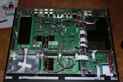
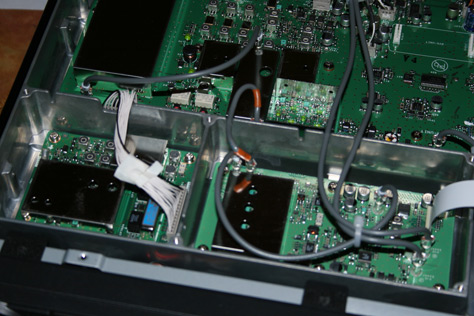
InstallationInstallation of the Scope Unit is straightforward on the FT-950: Remove the 18 screws holding on the radio's bottom cover. Untape the multi-pin cable from the empty (left front) slot in the bottom chassis. See photo at the left. Mount the Scope Unit with four screws provided. Plug in the 14-pin connector removed previously to J7002 on the Scope Unit. Remove coaxial cables G and H from the LOCAL and MAIN unit board plugs marked J4006 and J1029, respectively. The cable removed from G is inserted into the coaxial plug at the front center of the Scope unit. H is then inserted into the empty coaxial jack at the upper left off the Scope Unit. Make sure all cables are routed through the appropriate slots in the chassis so they are not pinched when the bottom cover is replaced. Replace cover and screws. |
|
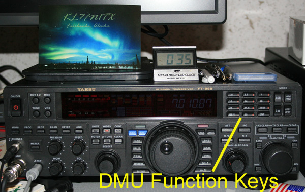
StartupOnce the unit is plugged into the back of the transceiver, the DMU-2000 should be powered on before the FT-950. When the radio's power switch is pressed, everything comes alive after a brief boot and check sequence. The first time the DMU-2000 is powered up, the built-in test will take about 45 seconds, but subsequent starts take about 10 seconds or less. As mentioned above, almost all operations on the DMU-2000 are available from the radio's front panel. To access these, press and hold the ENTER key on the BAND/FREQ keypad. The DMU menu tabs turn on, and keys 1-8 on the BAND/FREQ pad are used to navigate. |
|
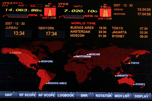
World MapInitial setup requires the user to select two "local times", which will be displayed all the time. The user can later select from a pre-loaded database of World Time Cities to display on the map. The user can choose whether or not to display the grayline. An OFF timer can be programmed for 15-120 minutes. A single alarm can be set to alert once or daily. Details of both VFOs on the FT-950 are displayed in the top quarter of the screen. Frequency, filter settings, and uTune status are readily discernible. Each press of the [8] key on the FT-950 is used to navigate menu levels for more or less functional detail. |
|
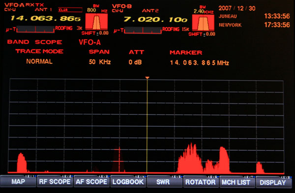
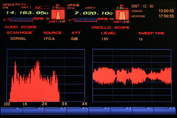
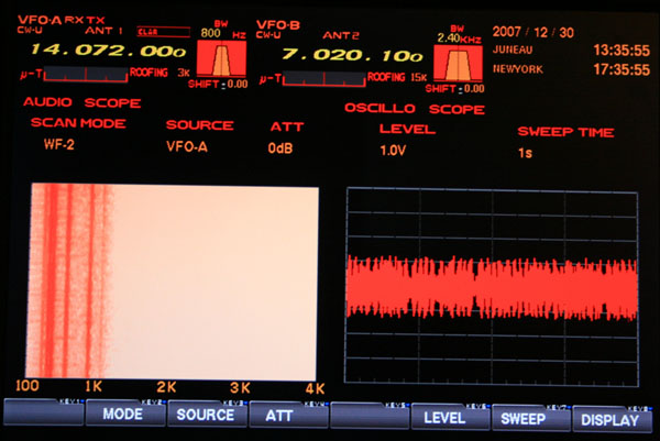
RF & Audio ScopesRigs in the $3000-and-up category often sport a so-called bandscope. The DMU-2000 shows the spectrum across spans from 25 kHz to 2.5 MHz centered on the FT-950's VFO-A frequency. Also, an entire band may be monitored, and band edges are definable. A "Limited Band Width Sweep" mode permits rapid acquisition of signals in a bandwidth selectable from 10% to 100% of the span. The vertical axis is 10 dB/div. During transmission, the RF waveform is displayed. Average and peak-hold modes may be selected in addition to real-time display of the surrounding frequencies. Markers showing the QMB memorized frequencies for the current band can be shown with white markers along the top horizontal. The Audio Scope contains both an audio spectrum and an oscilloscope display of the received audio. An external audio source is selectable via the mini-stereo plug on the back of the DMU-2000. The spectrum display is a very effective way to select and adjust the DSP filters. Sweep time on the oscilloscope is adjustable using the FT-950 front panel from 10 msec to 1 second. In addition, two waterfall displays (low and high speed) may be selected using the MODE [2] key. While the Audio Scope provides very useful information, it could be made more functional with a varying frequency spans and the ability to set tuning marks for digital modes. The user may choose from several screen color schemes to suit personal preferences and shack lighting. "Skins" and truly custom color schemes for the DMU-2000 interface would be nice-to-haves. Some work is needed on the function key fonts used on the screen, since F5 and F6 look the same on my LCD display. Unfortunately, it is not possible to capture and to store the spectrum, waterfall, or oscilloscope traces for later analysis. Recall and/or playback of the captured waveform (via AUDIO OUT jack) plus measurement tools would really make this a shack accessory like no other. The DMU-2000 is clearly upgrade-able, and hopefully Yaesu will pick up the hints. In addition, there is some inconsistency in menu choices between different DMU-2000 modes. While largely explicit if not intuitive, the controls in each mode do need an attentive operator when changing configurations.
|
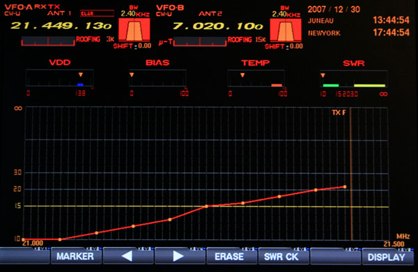 |
VSWRAntenna VSWR may be plotted across entire bands or band segments at intervals specified by the user. During normal operations, this display will show SWR as well as finals' temperature, bias voltage, and drain voltage. Automatic sweeping across the band at user-defined intervals would be far more convenient. Nay-sayers would argue the down side is potential for QRM, but the SWR measurements take a split second. No significant QRM would be generated. Export to a spreadsheet or screen capture and download would again be very useful here. |
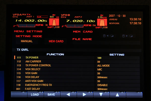 |
Menu ModePerhaps the most useful mode for the DMU-2000 is MENU. A brief press of the FT-950's MENU or C.S. buttons brings up an explicit menu of the rig's parameters. The same information will be displayed on the FT-950 front panel but in abbrevaited form. The DMU-2000 features a CF card reader on the front panel. A WIndows FAT16- or FAT32-formatted CF card can be used for file I/O on the unit. It's a good idea to back up the FT-950 configuration once set after some experimentation. Newbies and old hands alike are likely to have to reset the CPU, and the CF card can restore all menu settings. The CF card can also be used to transfer contact information for the LOGBOOK application.
|
I've been pondering how better to use the FT-950 and DMU-2000 combination. The awkwardness of the DMU controls is made a little simpler with a keyboard attached to the unit, but in the middle of a contest, the ergonomics are troublesome. I have also explored better use of VFO-A and -B. (The VFO-B tuning control is invoked by pressing the RX button to the upper left of the CLARIFIER/VFO knob.) I traditionaly work split using the clarifier RX/TX offsets, but I've come to realize the two-VFO combination is powerful. By combining different spectrum scope settings with band and types of operation, the DMU-equipped FT-950 is transformed into an even more impressive performer for contesters and DXers. Monitoring all or part of a band is simple. Flexing the VFOs to search for multipliers or for split operation becomes easier with the visual clues afforded on the scope display. |
|
|
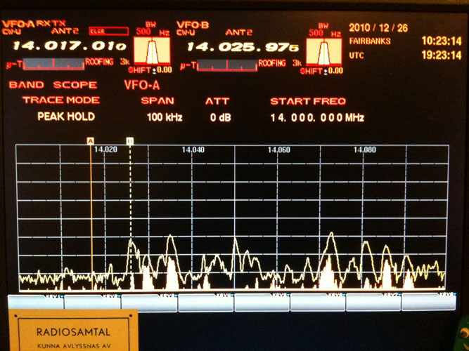
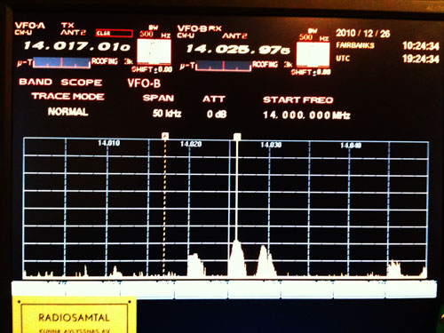
First a little review of the spectrum/band scope function is in order. The band scope shows the surrounding RF spectrum. There are two basic modes of operation. In CENTER or CF mode, the spectrum is displayed centered on the VFO frequency. This mode is in use in the photo above in the previous section. The span is 50 kHz, which shows +/- 25 kHz of the center frequency. The second band scope mode is FIXED, wherein the lower frequency of the display is specified by the user in the FT950 MENU under items 73 to 83 (SCOPE Group). The lower frequency for each band is a separate menu item. To the left you can see the scope shows activity from 14.0 to 14.1 MHz. The lower frequency is specified as 14000, and the span is 100 kHz. Frequencies for both VFOs are marked by vertical lines, and VFO settings are displayed at the top of the screen. Since the FT-950 was purchased three years ago, CENTER mode has been used exclusively. Recently I decided to try using FIXED mode to monitor an entire sub-band (e.g., CW), and I've come to like it. One very important discovery was that the band scope settings are saved by VFO and band. In other words, 160-6m bands can have different scope settings in both VFO-A and -B. A quick flip between the two VFOs can yield very different views of the band of interest. As shown in this photo, VFO-B is set to 50 kHz span. For CW DX work, coverage from 14.0 to 14.05 is nearly perfect for most of the action. For SSB work using VFO-A on 20m, I might set MENU 078 to 14150 kHz (bottom end of the band scope display) with a span of 250 kHz to cover the entire phone portion of the band. For a RTTY operation, MENU 078 would be set to 14050 kHz with a span of 100 kHz. Capability to store these different confiugrations and recall them from the DMU-2000 CF card make re-configuration easy. Note that BAND SCOPE SPAN SETTINGS ARE NOT SAVED. You have to set those up manually to suit your band/mode. Tweaks then become only minor nuisances. |