


|
|||||||||||
|
|
|
|
|
|
|
|
|
|||
May the Force (12) Be With YouBy Larry Ledlow, Jr. N1TX The challenges we all face living where we do and doing what we do just begin with sleepless days and nights during temperate weather trying to pack all that recreation in between those building and gardening chores. There’s a little matter of finding time for amateur radio work — the physical kind, not the on-air kind — before winter weather arrives. Lord help us when Aunt Sally shows up with the three kids and a grumpy husband smack in the middle of prime antenna season. The situation can seem almost hopeless. In late summer 2006, Justin KL1RL and I assembled a Force 12 EF-140 rotatable dipole. Unfortunately, as time slipped away, I had to re-prioritize and abandon any notion of installing it that year. WInter comes early to these parts, and the warm days were waning rapidly. A “Super Loop 80” delta from Radio Works would have to suffice on the low bands. However, I really, really, really wanted to get up a tri-bander, which would be important for contest season. So I turned to Force 12 again. For about a year on and off I studied various specifications and pricing for tri-banders. It’s easy to get obsessed with antenna performance specs, which cover the gamut from gain to front-to-back ratios. As an engineering professional, I have come to regard numbers on data sheets as highly suspect. Invariably there are unstated conditions under which the specs are true, and almost none of them reflect the real-world conditions of your installation. This isn’t to say it’s all nonsense, but I advise you not to stress over the decibel here and the decibel there on HF. My requirements evolved to a short list: 14/21/28 MHz coverage on a single boom; a cost of no more than around $1000; and a relatively compact size that could be assembled quickly and installed by one on the tower and one or two ground crew. This latter requirement proved to be a huge differentiator. It’s easy to be seduced by the dream of a “high-performance” tri-bander with a 30-plus-foot boom and full-sized elements. (And I say go for it if you have the resources!) Reality hit me hard when I thought more about the logistics of hauling such a monster up the tower and securing it in place. (Some of you may recall my plan is to have side-mounted antennas and use a switch to select direction.) The popular HyGain TH11DX, for instance, has a 37-foot boom, a 22-foot turning radius, and weighs just about 90 lbs! That’s a lot of work when you have to manage getting it around trees, guy wires, and various other obstructions within 45 feet of the tower. Yes, you can assemble something like this on the tower, but I think even those “smaller” sections really aren’t that much more manageable for a small crew. My investigations led me to look seriously at a couple of products from Optibeam (the OB7-3) and Force 12 (C3), both seven-element tri-banders with booms less than 20 feet long and weighing roughly 40 lbs. Ultimately, the C3 won out. The OB7-3 is about $1050 at today’s Euro-dollar exchange rate, and the C3 runs $759. Neither price includes shipping. With that information and by changing around a few other priorities, I figured I could stretch my budget to buy two C3s, one to aim Stateside, the other towards Europe. In addition, the C3 was delivered from California in about three weeks versus a potential 10- or 12-week wait for the Optibeam to be shipped from Germany. I had the C3s in hand by mid-August, but as mentioned earlier, various interruptions delayed assembly until early October. Shelley KL1SE, Dan KL1JP, and Rod KL1Y converged on the shack to put in a solid six hours in the fall chill to complete some badly needed ground work. Shelley worked on grounding and antenna switch box assemblies, Dan whacked trees and installed the Super Loop 80, and Rod began C3 construction. Each multiplexed with me on various tasks, and by the end of the “party”, we had made a major dent in the program plan. I completed one C3 after about two more hours on a subsequent day. With snow looming in the forecast, the second C3 would probably have to wait until spring. I estimate one C3 took about 5-6 man-hours to assemble, which included a thorough review of the instruction manual and an inventory of all parts for both antennas. The second should go together somewhat faster. The Force 12 C3 is shipped in nicely packaged bundles about four feet in length, which include boom sections and individual elements. Although I purchased two identical antennas, some parts are not readily interchangeable. Force 12 pre-drills and assembles the antennas at the factory. The rivet holes for elements and bolt holes in booms on antenna “A” will not necessarily align with corresponding holes in antenna “B” without re-drilling. This is not a criticism, though. The factory pre-assembly makes sure the antennas go together with minimal frustration, unlike some manufacturers’ products. Everything is well-marked, and should the need arise to cannibalize one antenna to repair another, the drilling should be very easy. As with the EF-140 dipole, the elements use tapered aluminum tubing and three rivet holes to secure each joint. The application of NOALOX to the inside overlapping section is easy with the included packet of anti-oxidant goo and a small brush. You insert the smaller section into the larger, align the three rivet holes in each, place the 1/8-inch rivets, and use your pop-riveter to finish the work. The 10m and 15m elements actually have four rivet holes on some inside tubing sections to allow you to lengthen or shorten these to adjust SWR suitable for your operating objectives within the band. This is especially important on the very wide 10m band, where the 2:1 bandwidth is about 1.5 MHz. The four sections of the 18-foot boom use bolts and “nylock” nuts. Each assembled element is bolted to the boom using U-bolts and welded L-brackets on left and right side of the main structure. UV-resistant PVC tubing fits over the center of each element to prevent crushing the aluminum tubing, yet the method provides a very secure hold. Force 12 does not supply a 1:1 balun with the antenna, but one is available as an option (Model B1/3S 3 kW version is $36.95), or you can make your own using several loops of coax. I preferred to purchase the Y1-5K 5 kW-rated current balun ($47.95) from Radio Works. The C3 manual recommends trimming any balun leads to around two inches. Any longer, and they may influence the tuning by making the 20m driver appear longer than it should be. I secured the balun to the two-inch boom using UV-resistant cable ties. In the end, I turned to materials available at local hardware and electrical supply stores. Galvanized SuperStrut metal framing channels are very handy for constructing just about any antenna or accessory mount to be installed on other structures. If you can build with the grandkids’ Legos or Tinker Toys, you can build with this stuff. It is manufactured by Thomas and Betts in a variety of finishes and configurations. You can download the catalog at the company web site noted at the end of the article. The material can be in short supply locally, particularly at the end of construction season, so plan ahead. I played with a few design ideas on paper. Then I bought a 10-foot section of 14-gauge slotted channel and cut two two-foot sections. These were to be mounted parallel and about two feet apart, each section face-side to the tower and secured with two U-bolts to the 1.25” tower legs. In the middle of each channel side (facing out), I decided to use two-inch clamps to mount a three-foot section of EMT conduit vertically. To this mast, I would secure the C3’s mounting plate using the included U-bolts. The big day for one final push was October 21. It was just about freezing, and the forecast called for freezing rain and snow later in the day. It would be nip-and-tuck all the way. Dan KL1JP and Gary Pearse NL7Y arrived late morning. While I gathered my tools, parts, and climbing harness, Gary and Dan began to partially disassemble the C3 boom into three sections. This would make hauling them up and avoiding obstacles easier. My first task was to re-locate a vertical V/UHF from the 60-foot level to a location just about 10 feet higher so I could have plenty of room for the C3. As I dangled and maneuvered I could see snow squalls closing in from the west. The pressure was on. While Connie KL1BE went for washers in Valley Center, Gary and Dan showed great innovation by scrounging some other stainless U-bolts from my VHF antennas on the ground. The problem’s solution had been determined quickly, but it was slow-going on the tower as my hands began to get cold. The remaining physical part was modest, because we assembled the beam on the tower by hauling it up in three element-boom subassemblies. I mounted the center boom section first onto the new mast and turned it 90 degrees. This would make bolt alignment easier, and the remaining sections hauled up vertically anyway. I slid the center section left and right while sliding on the front and rear sections. Gary pulled on the haul rope while Dan wrangled the dangling sub-assemblies with a lightweight Kevlar-core line. As I looked around me, snow was within a mile in all directions. NL7Y made a last inspection and pointed out the 15-meter driver had not been properly centered. Fortunately, access to the element was simplified by shifting it towards me by sliding the boom, and the problem was corrected. All nuts secured, I began the climb down the tower. Within minutes of stepping on the ground, freezing rain and snow began to fall. We would not see bare ground again until May. It was that close. After checking the SWR from ground level, all cables were connected and weatherproofed. The 20m VSWR was less than 1.5:1, while the 15m VSWR hit 1.7:1 at 21.4 MHz. The 10m VSWR is good from the bottom of the band up to about 28.5 MHz. I prefer CW anyway, so all systems were go right out of the box! I cannot thank Dan and Gary enough for their help this day. Naturally, the real proof is in the pudding. Dan and I turned on the radio and immediately heard a CE (Chile) S7, W5 in NM on CW, and a W7 in WA on an otherwise-dead 20m band. A number of RTTY contest stations were heard, but I don’t know where they were. Maintenance for these antennas should be minimal. Users on the internet report having to drill out and re-rivet elements after several years in the air. As the elements flex, the rivet holes will elongate. Installations in windy areas are more prone to this, of course. |
 |
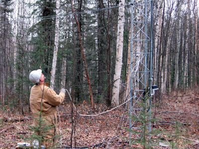 |
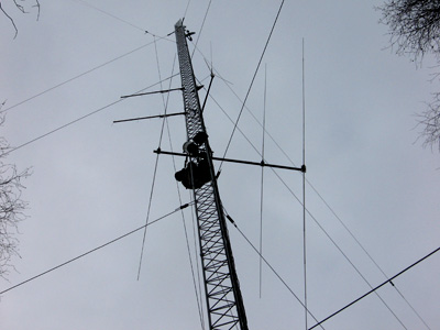
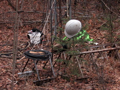
| After initial assembly, the C3 boom was taken apart in three pieces. Center section was mounted first, then slid left and right to add the back and front sections. | NL7Y on the haul rope pulling up one of the three boom sections with elements already mounted. KL1JP used a lightweight line to guide the sub-assemblies around the guy wires. |
 |
 |
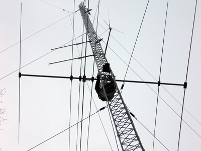
| After all three sub-assemblies were mated, the antenna was rotated 90 degrees to horizontal and secured. | Now the only thing left is to check the VSWR...and use it! In about a year, the C3 helped add over 5000 QSOs to the log. |